Chris D Shaw
Department of Computer Science, University of Regina
Regina, Saskatchewan S4S 0A2, Canada
Tel. (306) 585-4071
cdshaw@cs.uregina.ca
THRED [3,4]
is a simple two-handed free-form editor in which the user sits in
front of a workstation console, and is presented with a single
perspective view of the object updated in real time.
The user interacts with the model using a 3-button 3D tracker (bat)
in each hand.
The right bat![]() is used for picking and fine manipulation of vertices on the surface.
The left bat provides context by doing menu selection,
reorienting the model, and providing constraint mode and geometry.
is used for picking and fine manipulation of vertices on the surface.
The left bat provides context by doing menu selection,
reorienting the model, and providing constraint mode and geometry.
The simultaneous use of two sensors takes advantage of people's innate proprioceptive knowledge of where the two hands are in space. Guiard [2] gives psychophysical evidence for the idea that the left and right hands quite often act as elements in a kinematic chain. For right-handed people, the left hand acts as the base link of the chain. The right hand's motions are based on this link, and the right hand finds its spatial references in the results of motion of the left hand. Also, the right and left hands are involved in asymmetric temporal-spatial scales of motion (right hand for high frequency, left hand for low frequency).
THRED uses this natural division of manual labour by assigning the (low-frequency) setting of spatial context to the left hand, and the (high-frequency) selection and picking operations to the right.
Therefore, THRED is based on the strategy of splitting the effort according to Guiard's observations:
THRED uses a simple rectangular grid of vertices that can be hierarchically refined [1], with each vertex connected to its North, South, East and West neighbors. This rectangular edge connection scheme provides a collection of quadrilaterals (quads) that can be reshaped by moving one or more of their respective vertices. To generate flat polygons, each quad is subdivided into two triangles. Each quad can be recursively subdivided into exactly 4 sub-quads, resulting in 8 corresponding triangles. Selected vertices can be moved, and selected quads can be refined or erased. The user builds the desired surface by iteratively modifying, refining, and examining the surface given the available interface tools.
The right bat operations are
Control point selection is accomplished using the probe, which is attached to the right cursor. The probe is represented by a narrow cylindrical shaft, and the user controls the position and orientation of the probe with the right bat. The vertex that is closest to the probe axis is the current hot spot, and this vertex is highlighted by drawing an arrow from the intersection point on the surface to the hot spot. This highlight arrow lies in the surface of the triangle where the intersection occurs. The right image of figure 1 shows the probe and the hot spot arrow.
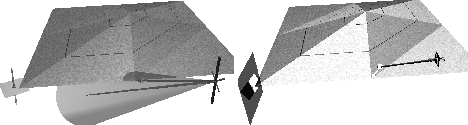
Figure 1: Left: Line constraint mode. Selected vertices
can only move
vertically. The right cursor shows the selection cone with its central
probe axis, and an arrow pointing from the cursor to the nearest
vertex.
Right: Plane constraint mode is active. Selected vertices may move in
the horizontal plane shown by the left cursor.
The probe on the right cursor intersects the surface, and the hot spot
is indicated by a small arrow from the intersection point.
If no objects intersect the probe axis, the probe visually switches to object selection mode, where the probe axis is drawn to some arbitrary length, and a translucent cone is drawn. Objects that fall within the cone are candidates for selection.

Figure 2: The button-enhanced Bat. From left to right are
the nose, dorsal and tail buttons.
Button 1 (the nose button) on the right bat allows rubber-band selection of rectangular collections of vertices. Right button 2 (the middle or dorsal button) grabs the selected vertices and uses the right bat to move them around in 3D. The currently-selected reshape operator is used to move the vertices. This movement can be constrained to move along a line or within a plane.
Pressing right button 3 (the tail button) grabs the selected vertices and uses the right bat to translate and rotate them in 3D. The translation component can be constrained to move along a line or within a plane.
The left bat does the following:
Constrained reshaping is controlled by first selecting which one of three modes is desired: no constraints, line constraints, or plane constraints. The left hand provides both the type of constraint and the geometry of the constraint. Clicking the left nose button moves from the current constraint mode to next in a three-step cycle.
Initially, the right cursor can manipulate vertices with all 3 positional degrees of freedom. When the left nose button is clicked, the system moves into line-constraint mode, in which right-handed reshaping operations are constrained along one of the three major axes. Both cursors change their shape to reflect line constraint mode, with the left cursor changing to a short pole through a square, and the right cursor adding a short pole that snaps to the current constraint axis (figure 1). The left cursor does not snap but remains tied to the left bat, because the canonical axis closest to the bat's Z vector (the pole axis in the left cursor) determines the constraint axis.
Thus while the left bat is geometrically stating the constraint axis, the right axis can be making a selection and starting the reshape operation. In order to avoid any inadvertent changes in snap axis, the constraint axis remains fixed while the reshape operation takes place, so the left hand does not need to hold a steady orientation during reshaping.
Similarly, in plane constraint mode the canonical plane of motion is stated continuously and directly by the orientation of the left hand, and remains constant while the right hand is doing a reshape. In this case, the right cursor shows a small square that is snapped to the constraint plane, and the left cursor shows a much larger snapped plane as shown in figure 1. The left cursor also has a small square rotating freely with the left bat, to help the user get to the desired orientation.
Pressing and releasing the left tail button attaches the surface to the left cursor, and allows the user to turn it around and look at it from all sides. Pressing and releasing the left tail button will detach the surface from the left hand.
Pressing the left dorsal button pops up a pie-shaped sundial menu. This menu allows you to select the reshape operator, to perform instant operations like refinement and deletion, and to control the display of the surface.
The sundial menu (figure 3) is a popup menu controlled by the orientation of the left bat. The menu choices are arrayed on the circular plate of the sundial, each on its own pie-shaped sector. The desired item is picked by pivoting the shadow stick about its base so that the stick's endpoint lies visually in front of the sector. The base of the shadow stick is located at the center of the plate, and when the menu first pops up, the stick is aligned with the line of sight, pointing directly at the user. Around the base of the stick is an inner circle which the user can point the stick at to indicate no selection. The position of the sundial is fixed rigidly to the bat, and the dial lies parallel to the screen.
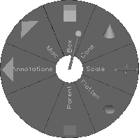
Figure 3: The sundial menu. Tandem (box) reshaping is
currently selected.
Clockwise from tandem is cone, scale, scale to median plane, adopt
parent, blank, the Annotations submenu and the Misc submenu.
Hierarchical menus are supported using the sundial menu. As figure 3 shows, a child menu is represented by an outward-pointing arrowhead. The user moves the shadow stick into the parent sector to pop up the child, which appears with the shadow-stick re-centered.
I conducted a user test comparing THRED to a mouse-based modeler with identical interaction style to the Alias Modeler. The Alias clone has the same underlying geometric structure, and the subjects were asked to complete a simple 3D modeling task many times using each editor. The task was to create a planar 3 by 3 grid of squares measuring 3 meters by 3 meters (1 meter on a side of each component square) from a single 1 meter square. The task consists of twice subdividing the first column and the first row of squares, then moving these squares about so that they measure 1 meter per side. This is essentially a 2D task that can be performed entirely in one orthographic view.
Users not trained in the use of bats but with 10 years of mouse experience were able to obtain approximately equal times with both interfaces after 5 trials.
The more complex task of folding a 1 meter cubed open box by deleting the corners and folding up the edges of the 3 by 3 planar grid yielded times twice as fast with THRED compared to the Alias clone.
Users spontaneously comment on how natural THRED is to use, and grow reasonably proficient in a short time, despite the initial difficulty that most experience in controlling the sundial menu.