Chapter Contents
Previous
Next
|
Chapter Contents |
Previous |
Next |
| LAN Environment |
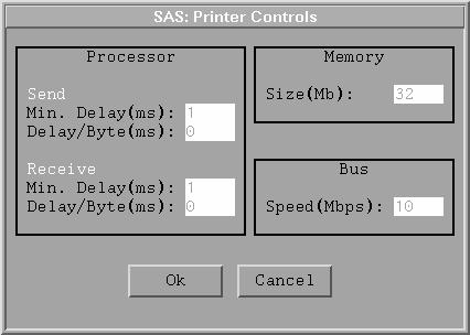
The simplest Computing Device model is the Printer equipment model. This model cannot generate independent data packets; therefore, its primary use in a LAN simulation is as a final destination for data packets from other Computing Device models. A sample control panel for a Printer model is shown in Figure 4.6.
delay = MinDelay * ( PacketSize * [Delay/Byte] )
Note that there is nothing in this model specific to a printer and since a
Printer model can only be a destination,
its properties (processor delays and bus speed) affect only the routing
protocol packets this model originates.
As with all Computing Device models,
you can display a window with processor traffic statistics using the
Options![]() Statistics selection from its pop-up menu.
Statistics selection from its pop-up menu.
|
Chapter Contents |
Previous |
Next |
Top |
Copyright © 1999 by SAS Institute Inc., Cary, NC, USA. All rights reserved.