7A60.10 Electron Diffraction
Concepts
Electron diffraction
Overview
Electron diffraction patterns for single crystal and polycrystalline materials are displayed on a CRT screen.

Details
Equipment
- [1] Electron diffraction tube
- [1] Video camera
- (Optional) [1] Graphite crystal model
Safety Equipment
- [2] Safety glove
Classroom Assembly
- Make sure the voltage and intensity knobs are turned all the way to the left.
- Turn on the power supply.
- Let the filament warm up for a minute or two at an anode voltage of 5 kV.
- Turn up the voltage up to your working level, to a maximum of 10 kV.
- Scan the screen for crystals using the horizontal and vertical controls.
- Fine tune the beam with one control at a time and adjust the intensity and focus controls after you have located a crystal. Do not exceed 10 μA!
- Set up the camera to view the screen.
- Turn down the voltage and intensity.
Important Notes
- Do not exceed 10 μA of current!
- The electron diffraction tube is fragile. Handle with care. Turn down the high voltage when not in use.
- It is worthwhile to contrast the diffraction of electrons with the diffraction of light by a two dimensional grid.
- Lift the demo with gloves. It's very heavy, and the leather strap on the handle has worn off.
Script
- Turn off the room lights.
- Turn up the voltage and intensity. Do not exceed 10 μA!
- Show the first diffraction pattern. Move the beam to look at the second diffraction pattern.
- Turn down the intensity and voltage. Turn off the electron diffraction demo.
- Turn on the room lights.
Additional Resources
References
- PIRA 7A60.10
- A different tube is used to demonstrate electron diffraction in a polycrystalline material in Video Encyclopedia 24-23.
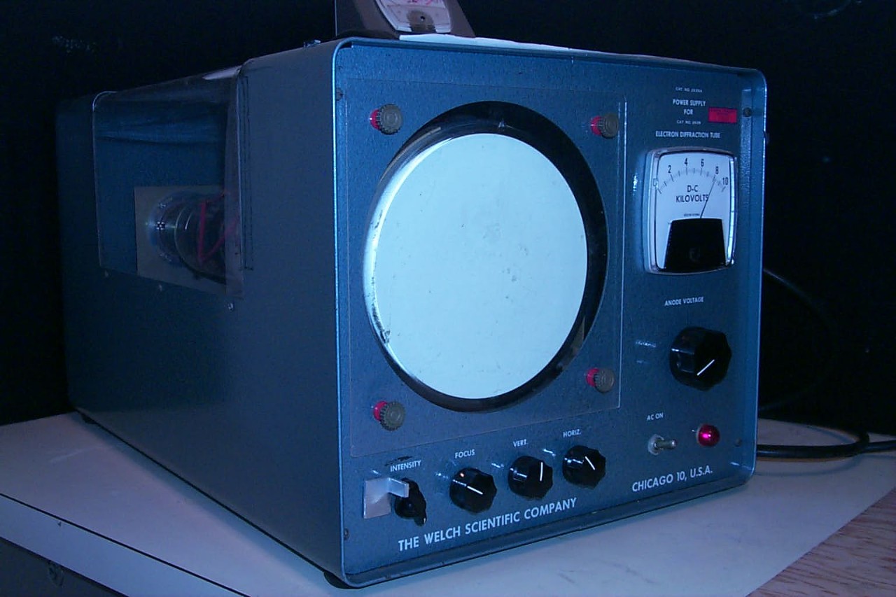
- The manual for the Welch 2639 is on file in the second year lab.
- The early development of the tube is described in a short note on page 549 of these conference proceedings:
H.F. Meiners and S.A. Williams in the "Proceedings of the American Association of Teachers: Thirty-First Annual Meeting," AJP 30, 549 (1962). - A photograph of a diffraction pattern obtained with this apparatus appears in "Quantum Mechanics," by Leslie Ballentine.
Disclaimer
- Don't attempt this at home!
Last revised
- 2026
Technicals
- We use a Welch model 2639 electron diffraction tube. The tube has graphite and aluminum foils mounted on a grid between the electron gun and the screen of the tube. The path of the electron beam may be varied so that the beam passes through one of the foils or misses both.
The aluminum is polycrystalline so that the diffraction pattern consists of rings. The graphite consists of small crystallites with the c-axis perpendicular to the surface of the foil so that the pattern consists of an array of spots with six-fold symmetry.
The accelerating voltage may be varied between 0 and 10 kV. The change in the spacing of the diffraction features with a change in voltage may be easily observed. It is necessary to adjust the position of the electron beam as the voltage is varied. - The focus knob doesn't work. Finding a single-crystal patch of graphite requires careful tuning.
Related AV
Related demos
If you have any questions about the demos or notes you would like to add to this page, contact Ricky Chu at ricky_chu AT sfu DOT ca.