3A70.25 Spring-Coupled Pendula
Concepts
Coupled oscillators
Overview
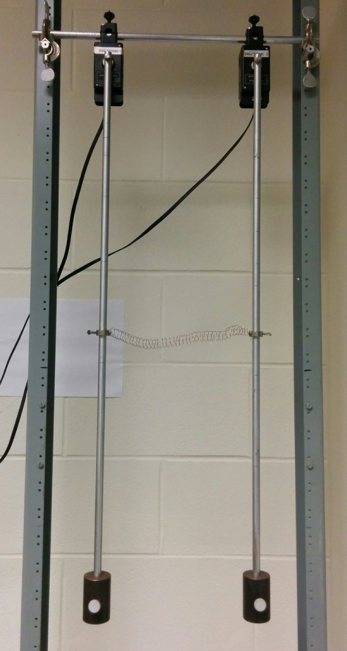
Two pendula oscillate, coupled together by a spring. The moments of inertia of the pendula can be adjusted by moving two masses. The coupling can be changed by changing the pivot separation and coupling points.
Details
Equipment
- [2] Rotational motion sensor
- [2] Pendulum rod with mounting hardware
- [2] Mass with set screw
- [1] Spring with clamps
- [2] Lab stand
- [2] 90-degree clamp
- [1] Aluminum rod
- (Optional) [1] Computer with Logger Pro
- (Optional) [1] LabPro or LabQuest Mini system
Classroom Assembly
- Mount the aluminum rod between the lab stands using the 90-degree clamps.
- Mount the rotational motion sensors on the aluminum rod.
- Attach the pendulum rods to the motion sensors.
- Attach the spring and the masses to the pendulum rods.
- (Optional) Connect the LabPro or LabQuest mini system to the motion sensors and the computer. If using the LabPro system, plug it into mains power.
Script
- Start with one pendulum stationary and the other moving.
- (Optional) Take data using Logger Pro.
- Observe the time evolution of the system.
- Change the system in some way (moment of inertia, coupling, initial conditions) and repeat the experiment.
Additional Resources
References
- PIRA 3A70.25
Disclaimer
- Don't attempt this at home!
Last revised
- 2022
Technicals
Related AV
Related demos
If you have any questions about the demos or notes you would like to add to this page, contact Ricky Chu at ricky_chu AT sfu DOT ca.