Chapter Contents
Previous
Next
|
Chapter Contents |
Previous |
Next |
| User Interface Features |
Arcs are used to connect simple equipment models logically, and their purpose is to represent paths or links between pieces of equipment. Arcs do not have any impact on the actual simulation of a network model other than their use in determining paths through the network. No arcs start or end on a compound model; however, there may be arcs between simple equipment models nested within compound models.
There are two ways to create an arc. One way is with a hotspot. Move the cursor over the right edge of a simple model in the netWorks drawing panel, and the cursor changes to a crosshair ("+"). If you click the left mouse button, the cursor has a rubberband line connected to it and to the equipment model. If you click the mouse while the crosshair cursor is over the drawing panel background, you put a bend in the arc. If you click the mouse while the crosshair cursor is over another simple model, an arc is created between the two models and the cursor reverts to its original state. Some of the simple models have a fairly small region associated with them, and it can be difficult to find the hotspot to change the cursor to a crosshair.
The other way to invoke the arc drawing process is through the equipment model's pop-up menu. If you position the cursor over a simple model and click the right mouse button, a pop-up menu appears. Selecting Arc from this menu invokes the arc drawing process.
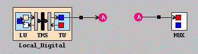
You may want to have an arc between two simple models that are far apart on the drawing panel. You can do this using the process that is described in the preceding paragraph, but the resulting arc may cross over other models and be visually distracting to your network model. Connector models are designed to alleviate this problem. A connector can be created either from a palette or from the drawing panel pop-up menu. You create a connector close to one of the models you want to link on the drawing panel and then duplicate (not copy) the connector using its pop-up menu. Move the duplicate connector close to the other equipment model and create an arc between the two. Remember to keep the direction for the arcs to and from the connector models consistent. (See Figure 2.7)
|
Chapter Contents |
Previous |
Next |
Top |
Copyright © 1999 by SAS Institute Inc., Cary, NC, USA. All rights reserved.