
Introduction
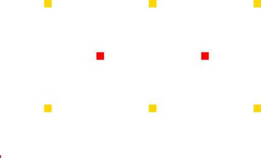
Figure 1: Layout illustrating the two types of fills. The POLY1 (red) is fill type A, and the POLY0 (yellow) is fill type B.
Often, one would like to fill a rectangle with etch holes, dimples, or other simple repetitive structure. This parameterized cell provides a simple approach to filling a rectangle with regularly spaced sub-rectangles or sub-circle.
The cell supports two types of fills: Type A and Type B. Type A fills are used, for example, for etch holes. The sub-rectangle or sub-circles are placed so that they are equidistant from each other, and the edges.
Type B fills are used, for example, for placing dimples. The dimples are equidistant from each other, but the distance between the edges of the rectangle and the nearest dimples is half the distance between the dimples
The fill donut parameterized cell is closely related.
Theory
Spacing
Before placing the sub-figures, the rectangle is divided into a number of regions, such that each region size is less than the spacing. The number of regions is calculated such that:
Above, c is the number of regions horizitonally, w is the width of the rectangle, and s is the maximum spacing. The rectangle is divided into region vertically using the same equation, but calculated using the height instead of the width.
The Type A fill places the subfigure, whether a rectangle or circle, on every intersection of the regions. The Type B fill places the subfigure in the center of every region.
Parameters
Any parameter may be modified, if necessary, to meet design rules. Typically, this involves increasing parameters that specify distances, so that minimum line width and minimum line spacing rules will not be violated. This has been extended to the convention of specifying a zero for some parameters to obtain an instance of the minimum size.
In addition to the parameters listed below, several technology parameters also influence the implementation of parameterized cells. This data must be present in the technology library.
| Name | Description | Range | Units |
|---|---|---|---|
| layer | This must be one of the drawing layers in the technology, and specifies the layer onto which the circle will be drawn. | dwg layers | - |
| width | The width of the rectangle to be filled. | [0,∞) | um |
| height | The height of the rectangle to be filled. | [0,∞) | um |
| spacing | This parameter specifies the maximum distance between sub-figures. However, the parameterized cells will try to minimize the number of sub-figures while ensuring that this limit is respected. | [0,∞) | um |
| layer_a | The drawing layer used to create the sub-figures used for fill Type A. If blank, then nothing will be drawn for this fill type. | dwg layers | - |
| size_a | This parameter is the width of the sub-rectangle or the diameter of the sub-circles, depending on which is selected. | [0,∞) | um |
| is_circle_a | If true, then the sub-figures for fill Type A will be circles. Otherwise, the rectangle will be filled with sub-rectangles. | true/false | - |
| layer_b | The drawing layer used to create the sub-figures used for fill Type B. If blank, then nothing will be drawn for this fill type. | dwg layers | - |
| size_b | This parameter is the width of the sub-rectangle or the diameter of the sub-circles, depending on which is selected. | [0,∞) | um |
| is_circle_b | If true, then the sub-figures for fill Type B will be circles. Otherwise, the rectangle will be filled with sub-rectangles. | true/false | - |
References
The documentation for this parameterized cell does not contain any references.
