
Introduction
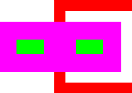
Figure 1: Layout for a standard staple hinge.
This parameterized cell draws a staple hinge. The cell allows attached structures to rotate upwards from the substrate in a full 180°.
The design of the parameterized cell closely follows the seminal design [1]. One customization is the addition of DIMPLE to the staple's wings, to reduce unwanted clearance.
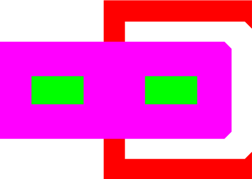
Figure 2: Layout for a staple hinge with chamfer.
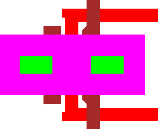
Figure 3: Layout for a dimpled hinge.
Theory
Clearance
Because of the fabrication method, the rotating rod in a staple hinge is not circular, nor is the staple. This can cause interference problems. One way to ensure that the staple can indeed rotate is to check its horizontal and tolerances.
Along the horizontal direction, with conformal growth of the second sacrificial layer, the POLY2 staple has the following space:
Meanwhile, the vertical distance is completely set by the thicknesses of the various process layers
Finally, by looking at the diagonal of the hinge's rod, the necessary distance is found to be:
With the above values, one can calculate the tolerance of the staple hinge.
Note that all of the variables, except for w, are process values (film thicknesses). Plotting the tolerance, T, as a function of the rod's width, reveals a maximium tolerance. For PolyMUMPs, this is at 3.25um.
Parameters
Any parameter may be modified, if necessary, to meet design rules. Typically, this involves increasing parameters that specify distances, so that minimum line width and minimum line spacing rules will not be violated. This has been extended to the convention of specifying a zero for some parameters to obtain an instance of the minimum size.
In addition to the parameters listed below, several technology parameters also influence the implementation of parameterized cells. This data must be present in the technology library.
| Name | Description | Range | Units |
|---|---|---|---|
| rod length | This is the width of the POLY1 rod. | [0,∞) | um |
| rod size | This is the length of the hinge's rod covered by the POLY2 staple. | [0,∞) | um |
| arm length | The distance between the center of the rod to the outside edge of the connecting beams. | [0,∞) | um |
| chamfer | This is the length along each corner that will be chopped off the terminals. Typically this value should be zero, but may be used to reduce spurious DRC violations with non-manhattan geometries. Not all corners are affected. | [0,∞) | um |
| dimple | If true, the DIMPLE layer is used to lower the 'wings' of the staple, reducing the possibility of the rod becoming trapped. Dimples on the rod are also added. | true,false | - |
