
Introduction
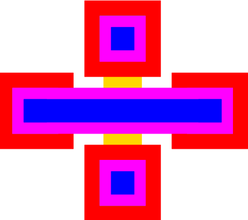
Figure 1: Layout of a simple bridge with one row and one pass.
Bridges are used to cross electrical signals. Using the "passes" and "rows" parameters, it is also easy to create signal taps for signal buses. It is designed to work with the standard PolyMUMPs conducting line.
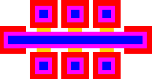
Figure 2: Layout of a bridge with one row and three passes.
The device consists of a POLY2 bridge, with METAL, that connects two terminals horizontally. A user specified number of passes connect pairs of terminals vertically using POLY0. Please also check the documentation for the pin parameterized cell.
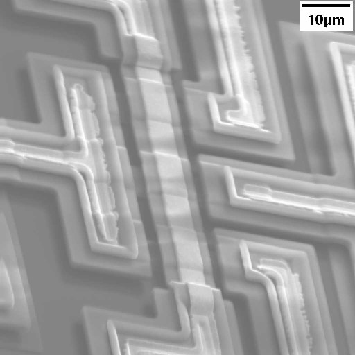
Figure 3: SEM of a bridge with three underpasses and one row.
Theory
Resistance
The resistance between the terminals connected using METAL should be quite low. However, the resistance for the underpasses may be significant. This resistance is due not only to the POLY0 resistance, but also the contact resistance between POLY0 and POLY1. The resistance can be calculated using the following formula:
Where, R is the resistance between terminals, l is the length of POLY0 separating the terminals, r0 is the resistivity of the POLY0, w is the width of the POLY0 underpass, and t is the thickness of the POLY0, A0,1 is the contact area between the POLY0 and the POLY1, and r0,1 is contact resistivity between POLY0 and POLY1.
The values for r0, r0,1, and t are process dependent, and can vary from process run to process run. However, for the PolyMUMPS process, t [1] has a nominal values of 0.5um. The resitivities are 1.5×10⁻³Ωcm for r0 and 3060Ωum2 for r0,1. The underpass for a cell with the default parameters would thus have a resistance of approximately 146Ω. Please note that the POLY0 resistivity can vary by as much as 50% in either direction.
The above calculation does not include the contact resistance between POLY1 and POLY2. Since most of the current will flow through the METAL layer, the current will need to pass through this interface. The POLY1-POLY2 contact resistivity is 1530Ωum2. Determining this resistance is more difficult. However, assuming that the current flows for a length twice the P1P2VIA width, then the additional resistance is 96Ω for a bridge with 20um wide pins. This comes from two terminals with a size of 4um by approximately 8um. This leads to a total resistance of approximately 242Ω.
Electrostatic Breakdown
The voltage difference between the different lines is governed by the dielectric breakdown of the surrounding material, typically air. The terminals will be spaced apart by the nominal spacing for POLY1 (3um). Another path for breakdown is the volume between POLY2 bridges and POLY0 underpasses. This distance is nominally 2.75um (SOX1 + SOX2). However, under the current Cronos process, the bridge height is often less.
Because of the small distances separating electrodes, the breakdown voltage must be determined using Paschen's curve [2]. While the exact breakdown voltage will vary depending on atmospheric humidity, etc., the breakdown voltage for electrodes spaced 3um apart should be over 500 volts. Counter-intuitively, the breakdown voltage under the bridges, where the separation is less, should be even higher.
Parameters
Any parameter may be modified, if necessary, to meet design rules. Typically, this involves increasing parameters that specify distances, so that minimum line width and minimum line spacing rules will not be violated. This has been extended to the convention of specifying a zero for some parameters to obtain an instance of the minimum size.
In addition to the parameters listed below, several technology parameters also influence the implementation of parameterized cells. This data must be present in the technology library.
| Name | Description | Range | Units |
|---|---|---|---|
| pin_size | This is the width of the POLY1 base of the device's terminals. This definition matches the pin size used for the pin parameterized cell. The pin size will automatically be increased, if necessary, to meet design rules | [0,∞) | um |
| passes | The number of vertical connections. | - | - |
| rows | The number of horizontal connections. The connecting terminals along the left will move inward by one each row to create a triangular structure suited for placement in a closely spaced set of conducting lines. The number of rows should be less than or equal to the number of passes. | [1,passes] | - |
| chamfer | This is the length along each corner that will be chopped off the terminals. Typically this value should be zero, but may be used to reduce spurious DRC violations with non-manhattan geometries. | [0,pin size/4) | um |
