
Introduction
A suspension is like a spring, designed to be compliant. However, they are also designed to be stiff in the perpendicular direction. This suspension has two stable resting points.
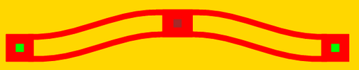
Figure 1: Layout of a bistable suspension.
Theory
Nothing yet.
Parameters
Any parameter may be modified, if necessary, to meet design rules. Typically, this involves increasing parameters that specify distances, so that minimum line width and minimum line spacing rules will not be violated. This has been extended to the convention of specifying a zero for some parameters to obtain an instance of the minimum size.
In addition to the parameters listed below, several technology parameters also influence the implementation of parameterized cells. This data must be present in the technology library.
| Name | Description | Range | Units | ||
|---|---|---|---|---|---|
| layer | Control the layer. | P1,P2,DT | - | ||
| length | The length of all of the compliant beams. | [0,∞) | um | + | + |
| width | The width of the compliant beams. | [0,∞) | um | + | + |
| deflection | The deflection of the beams from the center line. The total displacement from one state to the other will be twice this distance. | [0,∞) | um | + | + |
| shuttle_width | The width of the shuttle | [0,∞) | um | + | + |
| shuttle_length | The length of the shuttle. | [0,∞) | um | + | + |
| anchor width | The length of the compliant beams. | [0,∞) | um | + | + |
| include_poly0 | If true, a POLY0 ground plane will be included in the cell. The POLY0 ground plane can eliminate most electrostatic attraction between the suspension and the substrate bulk. | true/false | - | + | + |
