
Introduction
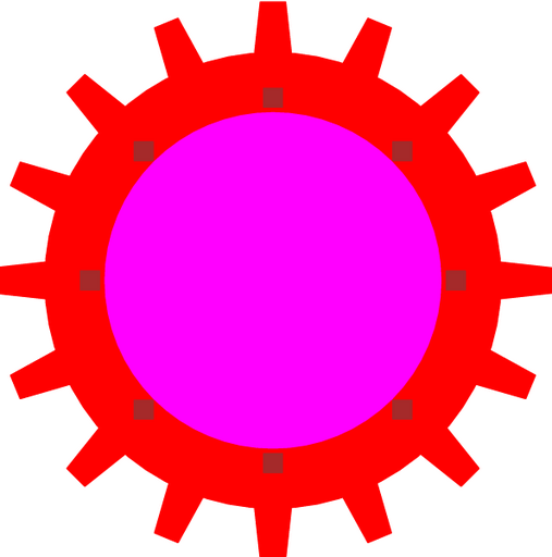
Figure 1: Layout for a gear design (40um radius).
This cell provides a toothed, rotating gear.
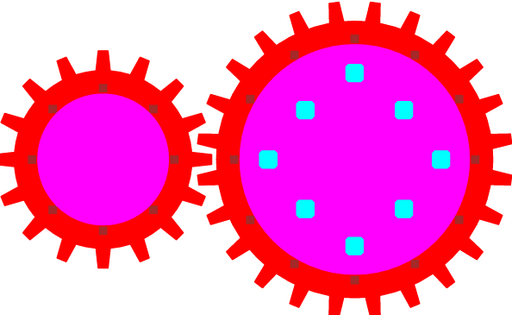
Figure 2: Design showing two gears of different sizes with intermeshed gears.
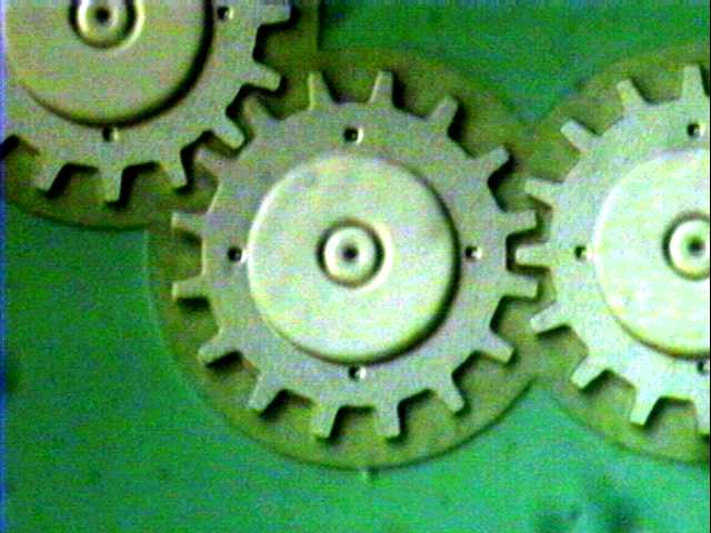
Figure 3: A gear with a radius of 40um (measured to mid-tooth). The gear teeth are 8um long and 4um wide at the outside.
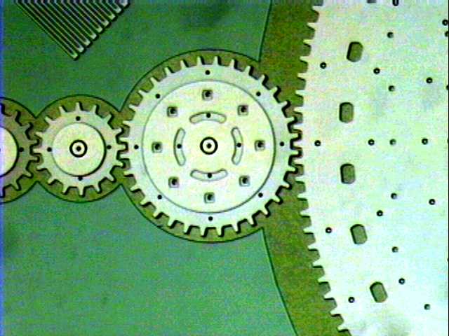
Figure 4: A gear with a radius of 80um (measured to mid-tooth). To the left are 40um radius gears and to the right is the edge of a 400um radius gear.
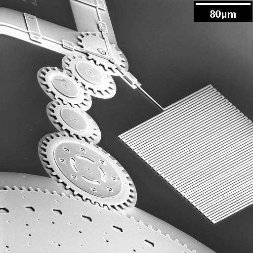
Figure 5: A gear train showing six gears.
Theory
Gear Trains - Meshing
Gear trains can easily be constructed by meshing the teeth. For the gear train to work, the teeth must be of the same size. Also, the spacing between the teeth must be the same. Thus, for two gears of different diameters, the following relation must hold:
For gears connected either horizontally or vertically, the angle that the teeth must be rotated can be calculated as follows:
Bowing
When creating large gears, one should be aware of stress gradients in the films. Stress gradients will cause bowing of the gear's wheel and flange. Since the wheel and flange are constructed from different poly-silicon layers, they will not have the same stress gradients and will thus exhibit different amounts of bowing.
epending on the direction of bowing, and the difference in the amount of bowing between the POLY1 and POLY2 layers, two effects may be observed. First, the bowing may cause the gear to seize if the wheel doesn't fit properly between the wafer surface and the hub. Second, the wheel may wobble (causing slippage) if the flange stop constraining its motion properly.
Parameters
Any parameter may be modified, if necessary, to meet design rules. Typically, this involves increasing parameters that specify distances, so that minimum line width and minimum line spacing rules will not be violated. This has been extended to the convention of specifying a zero for some parameters to obtain an instance of the minimum size.
In addition to the parameters listed below, several technology parameters also influence the implementation of parameterized cells. This data must be present in the technology library.
| Name | Description | Range | Units | P1 | DT |
|---|---|---|---|---|---|
| radius | The radius of the gear. This radius is measured from the center (obviously) to the mid-length of the teeth. Thus, the outer edge of the POLY1 wheel is radius + tooth_height / 2. | [0,∞) | um | + | + |
| tooth_height | This is the length of the tooth measured in the radial direction. | [0,∞) | um | + | + |
| tooth_width_o | This is the width of the tooth measured at the distance farthest from the centre. | [0,∞) | um | + | + |
| tooth_width_i | This is the width of the tooth measured at the base of the tooth. | [0,∞) | um | + | + |
| tooth_count | The number of teeth placed around the wheel. | [4,∞) | - | + | + |
| tooth_angle | The number of degrees to rotate the teeth. This parameter can be used to mesh gears together. | [0,360) | deg | + | + |
| include_poly0 | If true, a POLY0 ground plane will be included in the cell. The POLY0 ground plane can eliminate most electrostatic attraction between the bearing and the substrate bulk. | true/false | - | + | - |
References
The documentation for this parameterized cell does not contain any references.
