
Introduction
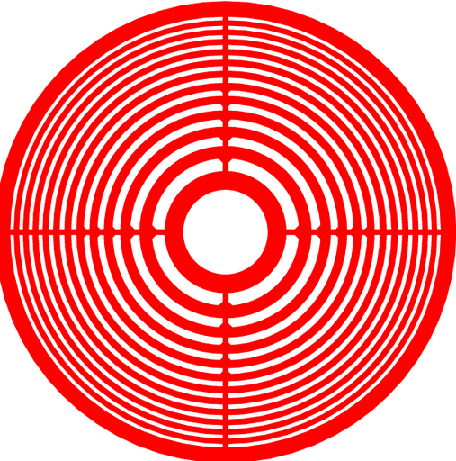
Figure 1: Layout for a Fresnel-zone plate with a circular frame.
This cell implements a Fresnel zone plate. A Fresnel zone plate has alternating transparent and opaque zones to create a binary amplitude diffractive optic element which can be used as a lens.
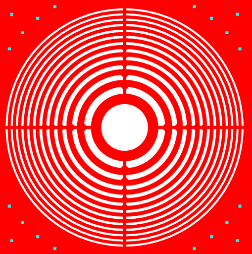
Figure 2: Layout for a Fresnel-zone plate with a square frame.
NOTE: Design rule errors will be found in this design. These errors occur near the structural supports for narrow rings. They indicate that some filling in the corners will occur. This filling will not affect the design.
Theory
Focal Length
The alternating regions of transparent and opaque regions are called Fresnel zones. By blocking every other zone, planar light passing through the plate will constructively interfere at the focal point. The zone radii required to achieve constructive interference at a distance f1 can be determined by the following equation [1]:
Where, Rn is the radius of the Nth boundary, λ is the wavelength of the light, and as above, f1 is the distance to the point of constructive interference. Where the wavelength λ is much greater than f1, then approximations can be made which lead to the second equation presented above.
To generalize, the FZP will act as a lens with a focal length of f1 for light with a wavelength λ. FZPs can thus be very useful for optics involving a monochromatic, or nearly monochromatic, light. Setting N=1 leads to a simple equation to determine the focal length from a FZP, f=f1=R12/λ.
However, unlike a standard lens that uses refraction, a FZP has multiple focal points. As one moves from the main focal point towards the plate along the axis, the same radius R1 actually covers more Fresnel zones. When one reaches the point half the length of f1 from the plate, the first zone actually covers two zones for the new position, where all light therefore destructively interferes. Continuing to one third of f1, the original R1 actually covers three Fresnel zones. Again, constructive interference occurs and an additional focal point can be found. However, the intensity at this point is only 1/9 the intensity at f1. The other focal points can be found by the following equation:
Transmission Efficiency
A FZP has a much lower transmission efficiency than a refractive lens. Even if the FZP is designed large enough to capture all of the light from the source (so we can ignore the effects of the lens' aperture), much of the light will be absorbed by the opaque sections of the FZP.
As a rough rule of thumb, the transmission efficiency can be approximated by the ratio of the opaque area to the total area of the FZP. Since the alternating rings of a FZP are of equal area, this indicates that the transmission efficiency of a FZP should 50% if N is even (neglecting the area taken up by the supports). In reality, additional light is lost as it is focused onto focal points other than f1.
Parameters
Any parameter may be modified, if necessary, to meet design rules. Typically, this involves increasing parameters that specify distances, so that minimum line width and minimum line spacing rules will not be violated. This has been extended to the convention of specifying a zero for some parameters to obtain an instance of the minimum size.
In addition to the parameters listed below, several technology parameters also influence the implementation of parameterized cells. This data must be present in the technology library.
| Name | Description | Range | Units | P1 | P2 | DT |
|---|---|---|---|---|---|---|
| focal_length | The focal length for the lens. Please note that this focal length really only applies to the specified wavelength and the lens will exhibit significant chromatic aberration. | [0,∞) | um | + | + | + |
| wavelength | The nominal wavelength of the light being focused by the lens. | [0,∞) | um | + | + | + |
| radius | This parameter determines the distance to the outer edge of the FZP. If the FZP has a square frame, then this parameter determine one half the edge length. For a circular frame, this parameter specifies the radius. | [0,∞) | um | + | + | + |
| outside_ring | The outside ring will be at least this wide. It may be desirable, for structural purposes, to ensure that the outside ring has a certain width. This value should be at least as great as the nominal width for the layer. | [0,∞) | um | + | + | + |
| square_frame | If this box is checked, the FZP will have a square frame. Otherwise, it will have a circular frame. | true/false | - | + | + | + |
