
Introduction
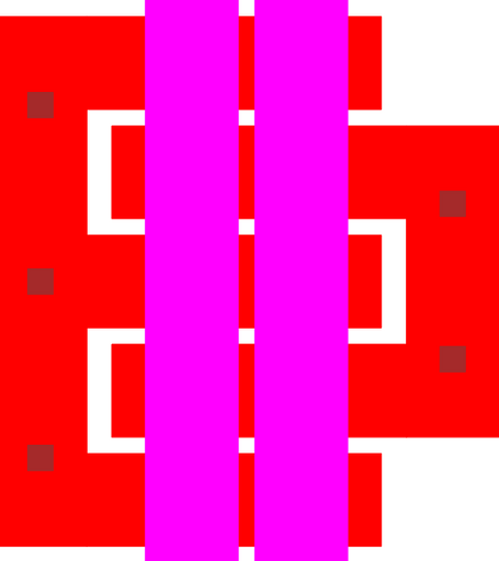
Figure 1: Layout for a downward moving scissor hinge.
This parameterized cell draws a scissor hinge. The cell allows attached two structures to rotate, with respect to each other, either downwards or upwards a full 180°.
The design of the parameterized cell closely follows the seminal design [1].

Figure 2: Layout for an upward moving scissor hinge.
Parameters
Any parameter may be modified, if necessary, to meet design rules. Typically, this involves increasing parameters that specify distances, so that minimum line width and minimum line spacing rules will not be violated. This has been extended to the convention of specifying a zero for some parameters to obtain an instance of the minimum size.
In addition to the parameters listed below, several technology parameters also influence the implementation of parameterized cells. This data must be present in the technology library.
| Name | Description | Range | Units |
|---|---|---|---|
| via_size | This is the size of the P1P2VIA rectangles used to connect the POLY1 and POLY2 bars. | [0,∞) | um |
| fingers | The number of interlocking fingers for one side of the hinge. The other side of the hinge will have one more finger. | [2,∞) | - |
| direction_down | This flag determines the direction that the scissor hinge can travel. | true,false | - |
| yoke_left | If false, the left side of the hinge will be left uncompleted. This allows designers to customize the connection. | true,false | - |
| yoke_right | If false, the right side of the hinge will be left uncompleted. This allows designers to customize the connection. | true,false | - |
