
Introduction
This cell implements the standard form of the Guckel electro-thermal actuator. It is a 'U' shaped structure that uses differential thermal expansion to achieve motion along the wafer surface.
When a voltage is applied to the terminals, current flows through the device. However, because of the different widths, the current density is unequal in the two arms. This leads to a different rate of Joule heating in the two arms, and thus to different amounts of thermal expansion. The thin arm is often referred to as the hot arm, and the wide arm is often referred to as the cold arm.
Backward deflection of the device is possible by temporarily delivering too much power to the device. Although too much power can easily destroy the device, at the right level the hot arm will plastically deform, decreasing its length. When the power is removed, the hot
There is also the option of including a "hook" on the end of the design. This hook is a proven design for connecting the actuator to a rod. A marker has been placed in the TMP layer to indicate where the rod should be connected.

Figure 1: Layout for a simple electro-thermal actuator

Figure 2: Layout for a simple electro-thermal actuator with a POLY0 ground plane.
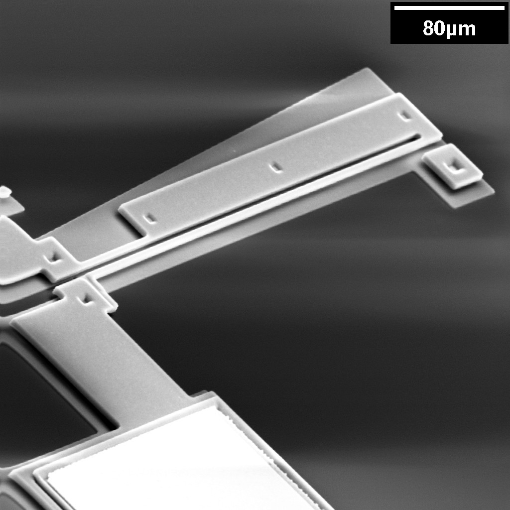
Figure 3: SEM of an electro-thermal actuator.
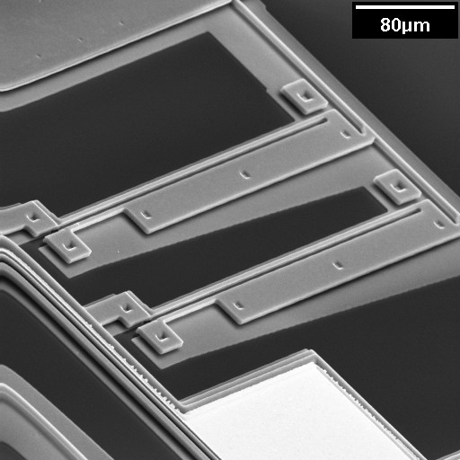
Figure 4: SEM of coupled electro-thermal actuator.
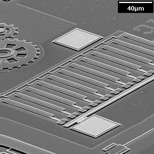
Figure 5: SEM of an array of electro-thermal actuator.
Theory
Electrical
The resistance of the actuator can be determined by the following equation:
Where, R is the total resistance, L is the total length of the actuator, F is the length of the flexure, t is the actuators thickness, wh is the width of the hot arm, wc is the width of the cold arm, wf is the width of the flexure, and ρ is the resistivity of the thermal actuator's material. The thickness t of the actuator will be either 2um or 3.5um, depending on whether the actuator is a POLY1 or double-thickness structure respectively. The exact value of the resistivity ρ should be determined from the process data, but for the PolyMUMPs process is on the order of 2×10⁻³Ωcm. A more accurate result can be obtained by replacing L with the total length less the width of the bar connecting the hot and cold arms (i.e. Length -> Length - Cross) for the wh term.
There is a major difficulty in apply the above equation. In thin beams (<10um wide), the resistivity will be significantly lower due to a phenomenon known as sidewall doping. This is due to increased doping at the sidewalls of the beams. The wider the beam, the smaller the effect of sidewall doping will be. Sidewall doping will affect 2-3um beams, but not significantly affect 50um beams. Since the hot arm and the flexure will be very narrow, their resistivity will be significantly less than the quoted value. Using the above equation will grossly overestimate actuators' resistance. Pleaser refer to [1] for more details.
Mechanical
A thermal actuator can be considered to be a cantilever. The cantilever has a no load deflection based on some input parameter (such as voltage or current). The following formula can be used:
Where, d is the deflection (length), d0 is the no-load deflection (length) and is a function of some input parameter a, C is the compliance (length per force), and f is the applied force. Typically, d0(0)=0.
Unfortunately, values for d0 have to be determined numerically. While a reasonable expression for the current density throughout the actuator could be found, the resistivity is a function of temperature. As the temperature will vary through out the device from room temperature to well over 1000°K, this cannot be ignored. Also, the coefficient of thermal expansion is also a function of temperature.
Determining the value of d0 requires an electro-thermal-mechanical simulation. Please refer to [1].
It should be possible to determine the compliance, C, of an actuator with a closed form equation. However, the actuator cannot be considered as a simple cantilever, and so a more advanced approach is required. However, the compliance can also be determined using numerical methods. A mechanical simulation, easily and quickly performed using Ansys, can be used to determine the compliance.
Double-thickness Actuators
Using the double-thickness actuator design will obviously lead to changes in properties.
Changes in the no-load deflection will depend on details that have been omitted here. For example, whether the actuator is under voltage control or current control.
However, changes to the compliance are easily determined, as it is directly related to the actuator's thickness.
Above, CP1 and CDT are the compliances of the POLY1 and double-thickness actuators respectively, and tP1 and tDT are the thicknesses of the POLY1 and double-thickness actuators.
Parameters
Any parameter may be modified, if necessary, to meet design rules. Typically, this involves increasing parameters that specify distances, so that minimum line width and minimum line spacing rules will not be violated. This has been extended to the convention of specifying a zero for some parameters to obtain an instance of the minimum size.
In addition to the parameters listed below, several technology parameters also influence the implementation of parameterized cells. This data must be present in the technology library.
| Name | Description | Range | Units |
|---|---|---|---|
| layer | This parameter is the drawing layer for the comb. These are POLY1, POLY2, or double-thickness structures. | P1/P2/DT | - |
| length | This is the distance from the terminals to the end of the actuator. It includes the cross, which connects the hot-arm to the cold-arm. It does not include the hook, which may or may not be present. | [0,∞) | um |
| flexure | The length of the segment along the cold-arm. | [0,length) | um |
| gap | The distance separating the cold and hot arms of the actuator. | [0,∞) | um |
| chamfer | The distance on the corners of the terminals to cut. | [0,∞) | um |
| width_c | The cold arm is composed of two segments. This is the width of the cold arm near the tip and should be relatively large. | [0,∞) | um |
| width_h | The width of the hot arm. This value should be near the minimum line width. | [0,∞) | um |
| width_f | The cold arm is composed of two segments. This is the width of the cold arm near the terminals and should be near the minimum line width, which is necessary for flexibility. | [0,∞) | um |
| cross | The width of the bar joining the cold and hot arms of the actuator at the tip. If less than the minimum width, this parameter will be automatically increased. | [0,∞) | um |
| actuation | This parameter is used to determine where the stop-line is placed. As the stop-line is does not affect the actual manufactured device, it can be ignored. However, the stop-line may provide an useful visual clue for design. | [0,∞) | um |
| pin_size | The side length of the terminals, which are square. Please refer to the documentation for the pin parameterized cell. | [0,∞) | um |
| include_stopper | Check this box to include a square stopper to prevent back deflection. | true/false | - |
| include_poly0 | If true, a POLY0 ground plane will be included in the cell. The POLY0 ground plane can eliminate most electrostatic attraction between the actuation and the substrate bulk. | true/false | - |
| include_hook | Check this box to include a hook. The hook is designed to be the minimum size that will still hold up to the maximum force available to pull a POLY1 rod. | true/false | - |
