
Introduction
This device is very similar to the horizontal heatuator. However, this device moves in a direction perpendicular to the wafer surface.
A vertical actuator can be design deflect downward. However, since it will only be a few micrometers from the wafer surface, its range of motion will be severely restricted. However, downward moving actuators can help structural assembly. If the actuator is operated with too much power, the hot arm will plastically deform and shorten. Power is then removed; the actuator will deflect past its original position.
If the tip of the actuator is placed underneath a free structure, the plastically deformed actuator will raise the structure from the surface. This may make it easier to raise.
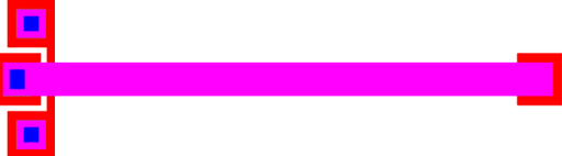
Figure 1: Design for a vertical actuator designed to deflect upwards.
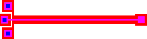
Figure 2: Design for a vertical actuator designed to deflect downwards.
Model 1: Design for a vertical actuator designed to deflect upwards.
Model 2: Design for a vertical actuator designed to deflect downwards.
Theory
Upward Actuating Heatuators
In processes where the second poly layer is conformally deposited, such as PolyMUMPs, upward moving actuators will have very poor performance. The second poly layer, which will be the wide arm, will not be flat. This greatly increases it's bending moment of inertia. This stiffens the wide arm against vertical bending.
Backbending
When heatuators are overdriven, they can undergo plastic deformation. This is particularly true for downward moving heatuators. Their range of motion is limited by the substrate surface. When overdriven, significant plastif deformation will occur in the hot arm. This effectively shortens the hot arm. When the current is removed, and the heatuator cools, the actuator will not return to its original position. It will instead deflect upwards because the hot arm is shorter.
Actuators provide greater force when backbending.
The plastic deformation matches the buckling of the hot arm when overdriven. It is therefore important to ensure that the hot arm buckles upwards. This can be partially supported by design the actuator so that the hot arm is wider then it is thick.
Parameters
Any parameter may be modified, if necessary, to meet design rules. Typically, this involves increasing parameters that specify distances, so that minimum line width and minimum line spacing rules will not be violated. This has been extended to the convention of specifying a zero for some parameters to obtain an instance of the minimum size.
In addition to the parameters listed below, several technology parameters also influence the implementation of parameterized cells. This data must be present in the technology library.
| Name | Description | Range | Units | ||
|---|---|---|---|---|---|
| length | This is the distance from the terminals to the end of the actuator. | [0,∞) | um | ||
| width_c | The width of the cold arm. | [0,∞) | um | ||
| width_h | The width of the hot arm. | [width_c,∞) | um | ||
| move_up | Check this box if you with the direction of actuation to be upwards. If unchecked, the actuator will deflect downwards when power is applied.. | true/false | - | ||
| pin_size | The side length of the terminals, which are square. Please refer to the documentation for the pin parameterized cell. | [0,∞) | um | ||
| chamfer | The distance on the corners of the terminals to cut. | [0,pin_size*0.25) | um | ||
| include_poly0 | If true, a POLY0 ground plane will be included in the cell. The POLY0 ground plane can eliminate most electrostatic attraction between the actuation and the substrate bulk. | true/false | - | + | + |
References
The documentation for this parameterized cell does not contain any references.
