
Introduction
For testing and measurement purposes, one often wishes to know how far an actuator, for example, has moved. This cell provides a convenient meter stick directly on the device surface for easy measurement. It consists of a rectangle in the desired structural layer with one side notched at a regular intervals.

Figure 1: Layout of a meter.
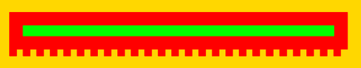
Figure 2: Layout of a meter that includes a POLY0 ground plane.
Model 2: Model of a meter that includes a POLY0 ground plane.
Parameters
Any parameter may be modified, if necessary, to meet design rules. Typically, this involves increasing parameters that specify distances, so that minimum line width and minimum line spacing rules will not be violated. This has been extended to the convention of specifying a zero for some parameters to obtain an instance of the minimum size.
In addition to the parameters listed below, several technology parameters also influence the implementation of parameterized cells. This data must be present in the technology library.
| Name | Description | Range | Units | P1 | P2 | DT |
|---|---|---|---|---|---|---|
| length | The length of the meter. The meter may actually be longer than specified if the specified length is not divisible by the layer's minimum width and spacing without remainder. | [0,∞) | um | + | + | + |
| include_poly0 | Check this box to include a POLY0 ground plane under the meter. | true/false | - | + | + | + |
References
The documentation for this parameterized cell does not contain any references.
