
Introduction
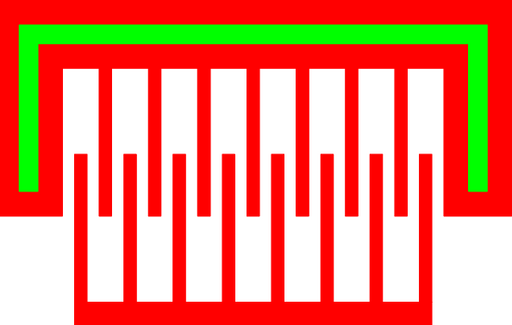
Figure 1: Layout of a simple bridge with one row and one pass.
The linear comb uses electro-static attraction to provide movement. It consists of a stator, which is fixed to the surface, and a rotor. The stator and rotor have a number of closely spaced finger which provide the electro-static attraction. Linear combs can also be used as a sensing element.
Theory
Force
The force applied on the rotor by the yoke is proportional to the change in capacitance with respect to displacement. Since the capacitance is a linear function of the finger overlap, the applied force is a constant for a given design an voltage.
For closely spaced fingers, a parallel approximation can be used to determine the capacitance and its derivative. This approximation is very limited, so exact results will require numerical analysis. The formula for the derivative is as follows:
Where, C is the capacitance, x is the finger overlap, ε is the permittivity of the intervening dielectric, h is the height of the fingers, and g is the gap between the fingers. To account for the approximations used in this formula, two extra parameters can be included, a and b, which are numerically determined [1].
For PolyMUMPS, several of the values are relatively fixed. The height of the fingers will be either 2.0um, 1.5um, or 3.5um, depending on whether the comb is constructed from POLY1, POLY2 or double-thickness poly-silicon respectively. Also, to maximize the comb's sensitivity, the gap will be the minimum spacing, or 2um. This leaves the number of fingers as the main method of controlling a comb's sensitivity.
The force applied on the rotor by the yoke, can be calculated by the following formula:
Where F is the applied force, dC/dX can be calculated as above, N is the number of fingers, and V is the applied voltage.
Note that N refers to the number of fingers on the rotor. This pcell implement the yoke with N-1 fingers. However, the anchored portion of the yoke wraps around the rotor so that it effectively provides N+1 fingers.
Parameters
Any parameter may be modified, if necessary, to meet design rules. Typically, this involves increasing parameters that specify distances, so that minimum line width and minimum line spacing rules will not be violated. This has been extended to the convention of specifying a zero for some parameters to obtain an instance of the minimum size.
In addition to the parameters listed below, several technology parameters also influence the implementation of parameterized cells. This data must be present in the technology library.
| Name | Description | Range | Units |
|---|---|---|---|
| layer | This parameter is the drawing layer for the comb. These are POLY1, POLY2, or double-thickness structures. | - | - |
| fingers | The number of fingers present on the rotor. The yoke will have one less finger, although it will wrap around the outside of the rotor providing two more pseudo-fingers. | [1,∞) | - |
| actuation | The desired distance that the actuator will be expected to move. | [0,∞) | um |
| overlap | The distance that the fingers from the rotor and the yoke will overlap when relaxed. | [0,∞) | um |
| stator_width | The width of the stator. | [0,∞) | um |
| rotor_width | The width of the rotor. | [0,∞) | um |
| include_dimples | The number of dimples that will be placed under the rotor. | [0,∞) | - |
| include_poly0 | If true, a POLY0 ground plane will be included in the cell. The POLY0 can eliminate most electrostatic attraction between the actuator and the substrate bulk. | [0,∞) | - |
