
Introduction
This parameterized cell draws a circle. However, it provides two advantages over the simple shape provided by Virtuoso. First, it calculates the number of sides necessary to meet the manufacturing tolerance. Second, it allows specification of a start and stop angle, allowing designers to draw partial circles.
The intelligence of the drawing algorithm is the primary benefit of this parameterized cell. Usually, curved surfaces have to be converted to polygons before they can be exported. Under standard procedure, the number of sides for each shape is a fixed parameter for the entire design. As can be seen from the theory section below, this is not the most efficient method of conversion.
Including too few points in the conversion can lead to design rule violations, which is a major issue. Alternatively, including too many points can create a large increase in the design size.
Theory
Tolerance
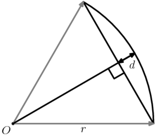
Figure 1: Geometry used to determine error between circular arc and straight line segment.
To determine the maximum angle that a line segment can span on a circle, while maintaining an upper bound, one must look at the maximum distance between a circular arc connecting two points and a linear segment connecting two points.
Rearranging the above equation gives the maximum angle a linear segment can span before the error exceed the tolerance d:
The maximum step between points on the perimeter of the circle is 2θ. One can find the number of points around the circle by finding the smallest integer, n, such that nθ≥2π. Once this number has been determined, a polygon with the correct number of sides can be easily generated.
In the case that the circular arc will not go entirely around the circle, the above procedure is modifed to find the smallest integer, n, such that 2nθ is greater or equal to the arc's angle.
Parameters
Any parameter may be modified, if necessary, to meet design rules. Typically, this involves increasing parameters that specify distances, so that minimum line width and minimum line spacing rules will not be violated. This has been extended to the convention of specifying a zero for some parameters to obtain an instance of the minimum size.
In addition to the parameters listed below, several technology parameters also influence the implementation of parameterized cells. This data must be present in the technology library.
| Name | Description | Range | Units |
|---|---|---|---|
| layer | This must be one of the drawing layers in the technology, and specifies the layer onto which the circle will be drawn. | dwg layers | - |
| radius | This parameter has the normal definition for a circle. While a value of zero can be specified, the radius will be increased, if necessary, to ensure that the circle does not violate any design rules. | [0,∞) | um |
| angle | This parameters controls what portion of the circle will be drawn. With, obviously, 360° specifying a full circle. | (0,360] | degrees |
| rotation | Cadence does not natively support rotations by increments other than 90°. To overcome this limitation, a rotation of up to 45° can be specified. Combined with the reflections about X and Y axes, any arc in any position can be drawn. | [0,45) | degrees |
| tolerance | This parameter specifies the upper limit on which the polygon generated to approximate the circle (or portion of a circle) can deviate from a true circle. While a value of zero can be specified, if the tolerance is less than half ot the technology's manufacturing grid, it will be increased before the circle will be approximated. | [0,radius] | um |
References
The documentation for this parameterized cell does not contain any references.
