
Introduction
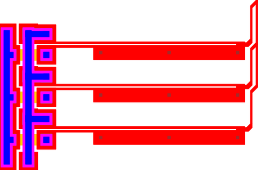
Figure 1: Layout for a team of electro-thermal actuators.
This cell implements a team of electro-thermal actuators. Each actuator is a Guckel electro-thermal actuator.
NOTE: The parameterized cells bridge and heatuator must be installed.
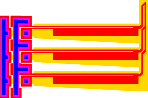
Figure 2: Layout for a team of electro-thermal actuators with ground planes.
Theory
Please also refer to the documentation describing the individual bridge and heatuator parameterized cells.
Electrical
The resistance of the heatuator array can easily be calculated if the individual heatuator resistance is known. They are connected electrically in parallel. For shorter heatuators, the underpass resistance from the bridge parameterized cell will need to be included.
Above, R is the resistance of the array, Rheatuator is the resistance of the heatuators, and Rbridge is the resistance of the bridge underpasses.
It should be noted that the heatuators are somewhat self-balancing. If any heatuators have a lower resistance, they will draw more current. These more conductive heatuators will thus heat more. Fortunately, resistance increases with temperature, imposing a limit on the current drawn.
Mechanical
From the heatuator theory, each individual heatuator has a deflection that can be calculated from the following formula:
Compliance is simply the inverse of the spring constant. Following the rules for spring combinations, and then converting back to compliance, the compliance of several cantilevers in connected in parallel is given by:
Here, the various Ci are the compliance of the cantilevers (heatuators) connected together, and Ceq is the overall compliance.
If all of the heatuators are identical, then the following expression can be used for the heatuator array:
Above, d0 is the no-load deflection of both the individual heatuators and the array, C is the compliance of the individual heatuators, N is the number of heatuators in the array, and f is the force applied to the array.
This last equation is an approximation as it neglects bending that occurs in the individual yokes connecting the heatuators together, which can be significant.
Parameters
Any parameter may be modified, if necessary, to meet design rules. Typically, this involves increasing parameters that specify distances, so that minimum line width and minimum line spacing rules will not be violated. This has been extended to the convention of specifying a zero for some parameters to obtain an instance of the minimum size.
In addition to the parameters listed below, several technology parameters also influence the implementation of parameterized cells. This data must be present in the technology library.
| Name | Description | Range | Units | P1 | DT |
|---|---|---|---|---|---|
| count | This parameter controls the number of heatuators included in the array. | [1,∞) | - | + | + |
| length | This is the distance from the terminals to the end of the actuator. It includes the cross, which connects the hot-arm to the cold-arm. It does not include the hook, which may or may not be present. | [0,∞) | um | + | + |
| flexure | The length of the segment along the cold-arm. | [0,length) | um | + | + |
| gap | The distance separating the cold and hot arms of the actuator. | [0,∞) | um | + | + |
| chamfer | The distance on the corners of the terminals to cut. | [0,∞) | um | + | + |
| width_c | The cold arm is composed of two segments. This is the width of the cold arm near the tip and should be relatively large. | [0,∞) | um | + | + |
| width_h | The width of the hot arm. This value should be near the minimum line width. | [0,∞) | um | + | + |
| width_f | The cold arm is composed of two segments. This is the width of the cold arm near the terminals and should be near the minimum line width, which is necessary for flexibility. | [0,∞) | um | + | + |
| cross | The width of the bar joining the cold and hot arms of the actuator at the tip. If less than the minimum width, this parameter will be automatically increased. | [0,∞) | um | + | + |
| actuation | This parameter is used to determine where the stop-line is placed. As the stop-line is does not affect the actual manufactured device, it can be ignored. However, the stop-line may provide an useful visual clue for design. | [0,∞) | um | + | + |
| pin_size | The side length of the terminals, which are square. Please refer to the documentation for the pin parameterized cell. | [0,∞) | um | + | - |
| pin_width | The side length of the terminals, which are square. Please refer to the documentation for the pin parameterized cell. | [0,∞) | um | - | + |
| pin_height | The height of the pin, which is measured from the gap to the outside of the POLY1. | [0,∞) | um | - | + |
| include_stopper | Check this box to include a square stopper to prevent back deflection. | true/false | - | + | + |
| include_poly0 | If true, a POLY0 ground plane will be included in the cell. The POLY0 ground plane can eliminate most electrostatic attraction between the actuation and the substrate bulk. | true/false | - | + | + |
