
Introduction
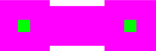
Figure 1: Layout for a staple without a POLY0 ground layer.
This cell implements a POLY2 staple. The device consists of single section of POLY2 that is anchored at both ends.
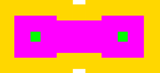
Figure 2: Layout for a staple with a POLY0 ground layer.
Theory
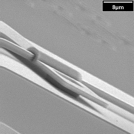
Figure 3: SEM of a staple.
The staple in implemented using POLY2. Except at the anchors, the POLY2 is deposited over the first two layer of sacrificial oxide (SOX). The thickness of SOX1 is 2um, and the thickness of SOX2 is 0.75um [1]. Thus, the POLY2 staple has a nominal height of 2.75um; however, because of over-etching (i.e. when removing POLY1), the height is usually less that the nominal height.
Because of the conformal topology of the PolyMUMPS process, rods underneath the staple can always move back forth along their axis. However, they may not necessarily be able to move sideways along the wafer surface. For example, POLY1 rods have a height of 2um and so can move freely between the two anchors. However, if the POLY1 rods are supported along their length by dimples, their height will be approximately 2.75um, the staple will impede any sideways motion.
 |
 |
 |
 |
 |
 |
 |
 |
Parameters
Any parameter may be modified, if necessary, to meet design rules. Typically, this involves increasing parameters that specify distances, so that minimum line width and minimum line spacing rules will not be violated. This has been extended to the convention of specifying a zero for some parameters to obtain an instance of the minimum size.
In addition to the parameters listed below, several technology parameters also influence the implementation of parameterized cells. This data must be present in the technology library.
| Name | Description | Range | Units |
|---|---|---|---|
| width | The width of the bridge connecting the two anchors. | [0,∞) | um |
| space | The distance between the two anchors. | [0,∞) | um |
| chamfer | This is the length along each corner that will be chopped. Typically, this parameter should is zero. However, it can be increased to reduced spurious DRC violations in non-manhattan geometries. Please note that under some circumstances, adding chamfer can create a staple with improperly sized notches. This condition should be readily noticeable upon inspection of the design. | [0,∞) | um |
| include_poly0 | Check this box to include a POLY0 ground plane. | true/false | - |
